Cathodic Protection Testing and Commissioning
Cathodic Protection Testing and Commissioning is the final stage before a newly installed or modified cathodic protection system is placed into normal operation.
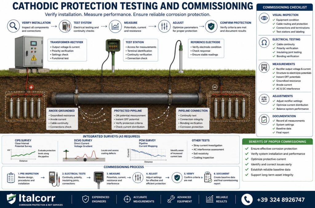
The purpose of commissioning is to verify that all components have been installed correctly, electrical connections are functioning as designed, protective current is distributed effectively and the protected structure achieves the required electrochemical protection criteria.
Italcorr provides testing, commissioning and performance verification of cathodic protection systems for pipelines, storage tanks, buried metallic structures and industrial infrastructure.
Objectives of Cathodic Protection Commissioning
Commissioning confirms that the installed cathodic protection system operates according to the design requirements.
The main objectives include:
- verification of system installation;
- inspection of electrical connections;
- confirmation of correct polarity;
- verification of cable continuity;
- testing of anode systems;
- measurement of groundbed resistance;
- verification of reference electrodes;
- testing of insulating joints;
- measurement of structure-to-electrolyte potentials;
- adjustment of transformer-rectifier output;
- verification of protective current distribution;
- identification of electrical interference;
- confirmation of cathodic protection effectiveness;
- establishment of baseline operating data.
The commissioning results provide the reference condition against which future inspections and maintenance measurements can be compared.
Pre-Commissioning Inspection
Before energizing the cathodic protection system, a detailed inspection of the installation should be performed.
The inspection may include verification of:
- transformer-rectifier installation;
- anode groundbed installation;
- sacrificial anodes;
- positive and negative cables;
- pipeline or structure connections;
- junction boxes;
- test stations;
- permanent reference electrodes;
- insulating joints;
- monitoring equipment;
- electrical bonds;
- grounding and protection devices.
Installation drawings and technical documentation can also be reviewed to confirm that the system corresponds to the approved design.
Visual Inspection
Visual inspection helps identify installation defects before electrical testing begins.
Typical checks include:
- condition of equipment enclosures;
- cable identification;
- terminal identification;
- mechanical protection of cables;
- cable gland installation;
- corrosion protection of connections;
- condition of test stations;
- accessibility of measurement points;
- equipment labeling;
- visible damage to components.
Any installation deficiencies identified during this stage should be corrected before final commissioning.
Cable Continuity Testing
Electrical continuity is verified for cables connecting:
- transformer-rectifiers;
- anode groundbeds;
- pipelines;
- storage tanks;
- test stations;
- reference electrodes;
- monitoring systems.
Cable continuity testing helps identify:
- broken conductors;
- incorrect connections;
- damaged cables;
- high-resistance connections;
- wiring errors.
Correct electrical continuity is essential for reliable cathodic protection operation.
Polarity Verification
Incorrect polarity is one of the most serious installation errors in an impressed current cathodic protection system.
Before energizing the system, polarity must be verified.
In a typical ICCP installation:
- the negative terminal is connected to the protected structure;
- the positive terminal is connected to the anode system.
Incorrect polarity can cause accelerated corrosion of the structure instead of protecting it.
For this reason, polarity verification is a critical commissioning activity.
Transformer-Rectifier Testing
For Impressed Current Cathodic Protection (ICCP) systems, the transformer-rectifier unit is tested before and during commissioning.
Measurements may include:
- AC input voltage;
- DC output voltage;
- DC output current;
- operating settings;
- polarity;
- electrical connections;
- protective devices;
- grounding;
- enclosure condition.
The rectifier should initially be energized under controlled conditions and its output gradually adjusted while monitoring the response of the protected structure.
Anode Groundbed Testing
The anode groundbed is a key component of an impressed current system.
Commissioning tests may include:
- groundbed resistance measurement;
- verification of anode cable continuity;
- measurement of total current output;
- measurement of individual anode currents where possible;
- inspection of junction boxes;
- verification of cable connections;
- comparison with design values.
Unexpectedly high groundbed resistance may indicate installation problems, poor soil contact, cable defects or unsuitable ground conditions.
Sacrificial Anode Testing
For galvanic cathodic protection systems, commissioning includes verification of sacrificial anode operation.
Measurements may include:
- structure-to-electrolyte potential;
- anode-to-electrolyte potential;
- anode current output;
- circuit resistance;
- electrical continuity;
- polarity and connection verification.
The measurements confirm that the installed anodes are delivering protective current to the structure.
Reference Electrode Verification
Permanent reference electrodes are often installed for monitoring pipelines, tanks and other protected structures.
Before relying on their readings, they should be verified against an appropriate portable reference electrode.
Commissioning may include:
- stability verification;
- comparison measurements;
- cable continuity testing;
- polarity verification;
- confirmation of correct installation position.
Reliable reference electrodes are essential for accurate long-term cathodic protection monitoring.
Test Station Verification
All cathodic protection test stations should be inspected during commissioning.
Verification may include:
- terminal identification;
- cable continuity;
- pipeline connections;
- reference electrode connections;
- coupon connections;
- bond connections;
- enclosure condition;
- correspondence with electrical drawings.
Correct labeling is particularly important for future maintenance and monitoring.
Insulating Joint Testing
Insulating joints are used to electrically separate protected pipeline sections from other metallic systems.
Commissioning tests can verify that the required electrical isolation has been achieved.
Testing may identify:
- short-circuited insulating joints;
- unintended metallic bypasses;
- grounding connections;
- incorrectly connected surge protection devices;
- electrical continuity through external structures.
A defective insulating joint can significantly change cathodic protection current distribution.
Initial Structure-to-Electrolyte Potential Measurements
Before energizing the cathodic protection system, baseline or native potentials can be measured.
These measurements provide information about the natural electrochemical condition of the structure before protective current is applied.
After the system is energized, new measurements are performed to determine the effect of cathodic protection.
Comparison of native and protected potentials provides useful commissioning information.
ON Potential Measurements
After energization, ON potentials are measured while the cathodic protection system is operating.
These measurements help evaluate:
- initial current distribution;
- response of the protected structure;
- areas receiving insufficient current;
- areas receiving excessive current;
- overall system behaviour.
The transformer-rectifier output can then be adjusted progressively based on the measured response.
Instant OFF Potential Measurements
Where appropriate, synchronized current interruption can be used to measure instant OFF potentials.
Instant OFF measurements reduce the influence of voltage drop in the electrolyte and provide a more representative assessment of polarization.
For systems influenced by multiple cathodic protection sources, synchronized interrupters may be required.
Measurements can then be compared with the applicable cathodic protection criteria and project requirements.
Adjustment of System Output
Cathodic protection commissioning is not simply a matter of switching the system on at maximum output.
The system should be adjusted to provide adequate protection while avoiding unnecessary or excessive current.
Adjustment may involve:
- transformer-rectifier voltage;
- transformer-rectifier current;
- individual anode circuits;
- electrical bonds;
- drainage systems;
- interference mitigation systems.
The objective is to achieve stable and effective current distribution throughout the protected structure.
Current Distribution Verification
A cathodic protection system may provide adequate potentials near the current source while distant sections remain insufficiently protected.
Commissioning therefore includes verification of current distribution across the complete protected structure.
Measurements can be performed at:
- test stations;
- pipeline extremities;
- insulating joints;
- crossings;
- branches;
- critical structures;
- remote monitoring points.
Where necessary, detailed surveys can be performed to evaluate areas between permanent measurement points.
CIPS During Commissioning
For long buried pipelines, CIPS (Close Interval Potential Survey) can provide detailed verification of cathodic protection performance after system commissioning.
CIPS provides closely spaced measurements along the pipeline and can identify:
- under-protected sections;
- excessive potential variations;
- areas of poor current distribution;
- possible interference;
- sections requiring system adjustment.
CIPS can therefore provide a valuable baseline survey for future comparison.
DCVG During Commissioning
A DCVG (Direct Current Voltage Gradient) Survey may be performed to identify coating defects after pipeline construction.
Construction activities, backfilling or handling can damage the pipeline coating.
DCVG can locate coating defects that may increase cathodic protection current demand and reduce overall system efficiency.
Repairing significant coating defects before final acceptance can improve long-term cathodic protection performance.
PCM During Commissioning
PCM (Pipeline Current Mapping) can be used to evaluate signal current attenuation along a newly installed or existing pipeline.
PCM can help identify:
- unexpected current losses;
- coating deterioration or construction damage;
- electrical contacts;
- unintended grounding;
- abnormal pipeline sections.
PCM data can complement CIPS and DCVG results during comprehensive commissioning.
Stray Current Investigation
External DC electrical systems can affect cathodic protection commissioning results.
Potential interference sources include:
- electrified railway systems;
- neighbouring cathodic protection systems;
- industrial DC equipment;
- grounding systems;
- other buried metallic structures.
Potential fluctuations and current measurements can be performed to determine whether external interference affects the protected structure.
AC Interference Assessment
Pipelines located near high-voltage AC power lines may be exposed to induced AC voltage.
Commissioning may therefore include:
- AC pipe-to-soil voltage measurements;
- verification of grounding systems;
- testing of mitigation devices;
- verification of decoupling equipment;
- assessment of AC interference conditions.
This is particularly important for pipelines sharing corridors with high-voltage transmission systems.
Commissioning of Remote Monitoring Systems
Where cathodic protection remote monitoring equipment is installed, its operation should also be verified during commissioning.
Testing may include:
- potential measurement channels;
- rectifier voltage monitoring;
- rectifier current monitoring;
- alarm functions;
- communication systems;
- data transmission;
- power supply;
- synchronization;
- remote control functions where applicable.
The values transmitted remotely should be compared with direct field measurements.
Stabilization and Polarization
After initial energization, the protected structure may require time to reach stable polarization conditions.
For this reason, commissioning may include measurements performed at different stages:
Before energization — native potentials.
Immediately after energization — initial response.
After stabilization — evaluation of established cathodic protection conditions.
The required stabilization period depends on the structure, coating condition, electrolyte and cathodic protection system.
Cathodic Protection Criteria
Commissioning results should be evaluated according to the applicable technical standards, specifications and project requirements.
Depending on the structure and environment, assessment may consider:
- structure-to-electrolyte potential;
- polarization shift;
- instant OFF potential;
- current density;
- stability of protection;
- interference conditions.
No single measurement should be interpreted without considering the complete electrical and environmental conditions of the protected structure.
Troubleshooting During Commissioning
If the required protection criteria are not achieved, systematic troubleshooting is performed.
Possible causes include:
- insufficient rectifier output;
- high anode groundbed resistance;
- cable damage;
- incorrect connections;
- poor electrical continuity;
- coating defects;
- defective insulating joints;
- unintended grounding;
- electrical contact with other structures;
- interference from neighbouring systems;
- incorrect system design parameters.
Additional measurements can be used to identify the cause before corrective actions are implemented.
Final Performance Verification
After all adjustments and corrective actions are completed, final measurements are performed.
The final verification may include:
- transformer-rectifier output;
- structure-to-electrolyte potentials;
- ON potentials;
- instant OFF potentials;
- anode current;
- groundbed resistance;
- insulating joint performance;
- reference electrode verification;
- electrical continuity;
- interference measurements.
These results establish the initial operating condition of the cathodic protection system.
Commissioning Documentation
Complete commissioning documentation provides an important technical reference for future operation and maintenance.
The final documentation may include:
- system description;
- design parameters;
- equipment identification;
- installation verification;
- transformer-rectifier settings;
- groundbed resistance;
- anode measurements;
- native potentials;
- ON potentials;
- instant OFF potentials;
- insulating joint test results;
- reference electrode verification;
- interference measurements;
- CIPS, DCVG or PCM results where performed;
- identified deficiencies;
- corrective actions;
- final system settings;
- photographs;
- measurement tables;
- recommendations for future monitoring.
Baseline Data for Future Maintenance
One of the most important outcomes of commissioning is the creation of reliable baseline data.
Future inspections can be compared with these initial measurements to identify:
- increasing groundbed resistance;
- changes in rectifier output;
- coating deterioration;
- decreasing protection levels;
- reference electrode drift;
- development of interference;
- changes in current distribution.
Good commissioning documentation therefore contributes directly to preventive maintenance and long-term asset integrity management.
Applications
Italcorr provides cathodic protection testing and commissioning for:
- gas pipelines;
- oil pipelines;
- water pipelines;
- firewater pipelines;
- industrial pipelines;
- aboveground storage tanks;
- underground tanks;
- buried metallic structures;
- steel foundations;
- industrial facilities and utility networks.
Integrated Testing and Commissioning
For complex pipeline systems, Italcorr can combine commissioning measurements with specialized field surveys:
Cathodic Protection Testing
Electrical and electrochemical verification of the installed system.
CIPS Survey
Detailed assessment of protection potentials along the pipeline.
DCVG Survey
Identification of coating defects that may affect current demand.
PCM Survey
Evaluation of current attenuation and electrical anomalies.
Insulating Joint Testing
Verification of electrical isolation.
Stray Current Investigation
Assessment of external DC interference.
AC Interference Assessment
Evaluation of induced AC effects.
This integrated approach provides a comprehensive assessment before the cathodic protection system enters normal operation.
Why Proper Commissioning Matters
Correct commissioning helps to:
- confirm that the system has been installed correctly;
- identify installation defects before operation;
- verify cathodic protection effectiveness;
- optimize protective current distribution;
- avoid unnecessary overprotection;
- identify electrical interference;
- establish reliable baseline measurements;
- reduce future maintenance costs;
- increase system reliability;
- support long-term corrosion control;
- extend asset service life.
Italcorr Cathodic Protection Testing and Commissioning
Italcorr provides comprehensive testing, commissioning and performance verification of cathodic protection systems, from initial electrical inspection to final system adjustment and documentation.
By combining electrical testing, structure-to-electrolyte potential measurements and specialized pipeline surveys such as CIPS, DCVG and PCM, Italcorr verifies that cathodic protection systems operate effectively and provides reliable baseline data for future monitoring and maintenance.