
Stray Current Interference
Stray Current Interference is an important corrosion risk for buried metallic pipelines and other electrically continuous structures located near DC electrical systems.
Stray currents are electrical currents that leave their intended circuit and flow through the soil, water or neighbouring metallic structures. When these currents enter and subsequently leave a buried pipeline, they can cause significant changes in structure-to-electrolyte potential and, at current discharge locations, may lead to accelerated corrosion.
Italcorr provides stray current interference investigation, monitoring and mitigation services for pipelines, storage facilities and buried metallic infrastructure, with particular attention to the interaction between external DC sources and cathodic protection systems.
Stray Current Interference and Corrosion
A buried metallic structure can unintentionally become part of an external electrical circuit.
Stray current may enter the structure at one location, travel through the metal and leave the structure at another location.
The location where current enters the pipeline generally becomes more cathodic, while the location where current leaves the pipeline may become anodic.
The discharge area is particularly important because accelerated metal loss can occur where DC current leaves the structure and returns to the surrounding electrolyte.
The resulting corrosion can be highly localized and may develop significantly faster than ordinary soil corrosion.
Main Sources of Stray Current Interference
Potential sources of stray current include:
- electrified railway systems;
- tram and metro networks;
- DC traction systems;
- neighbouring cathodic protection installations;
- industrial DC power systems;
- welding installations;
- DC grounding systems;
- mining and industrial electrical equipment;
- other buried pipelines with impressed current cathodic protection.
The effect on a pipeline depends on the current magnitude, distance from the source, soil resistivity, coating condition and electrical configuration of the surrounding infrastructure.
DC Traction Systems
Electrified railway, metro and tram systems are among the most common sources of dynamic stray current interference.
Traction current should return to the electrical substation through the rails. However, part of the current may leak from the rails into the surrounding soil.
Buried pipelines located near the railway can provide a lower-resistance return path.
The current may:
enter the pipeline near one location → travel along the pipeline → leave the pipeline at another location → return toward the traction system.
Because train position and power demand change continuously, pipeline potentials may fluctuate rapidly.
Continuous monitoring is therefore often necessary to correctly evaluate this type of interference.
Interference from Cathodic Protection Systems
Impressed Current Cathodic Protection systems can also influence neighbouring buried structures.
Protective current discharged from an anode groundbed travels through the soil toward the protected structure.
A nearby foreign pipeline may intercept part of this current.
Depending on the geometry of the structures and current flow, the foreign pipeline can experience:
- positive or negative potential shifts;
- current pickup;
- current discharge;
- unstable protection conditions;
- localized corrosion risk.
Interference studies are particularly important where several cathodically protected pipelines share the same corridor.
Static and Dynamic Stray Current
Stray current interference can generally be divided into two categories.
Static Interference
Static interference produces relatively stable potential shifts.
Typical sources may include neighbouring impressed current cathodic protection systems or continuous industrial DC installations.
Dynamic Interference
Dynamic interference varies with time.
Typical sources include:
- railway traffic;
- tram and metro systems;
- variable industrial processes;
- periodically operating DC equipment.
Dynamic interference can require high-frequency or long-duration data logging because occasional manual measurements may not capture the most critical conditions.
Signs of Possible Stray Current Interference
Stray current interference may be suspected when measurements show:
- rapid pipe-to-soil potential fluctuations;
- repeated positive potential excursions;
- correlation with railway operation;
- abnormal differences between neighbouring test stations;
- unexpected changes in cathodic protection current;
- unstable rectifier behaviour;
- unusual current direction;
- localized corrosion not explained by normal environmental conditions.
Historical corrosion failures can also provide important evidence when selecting monitoring locations.
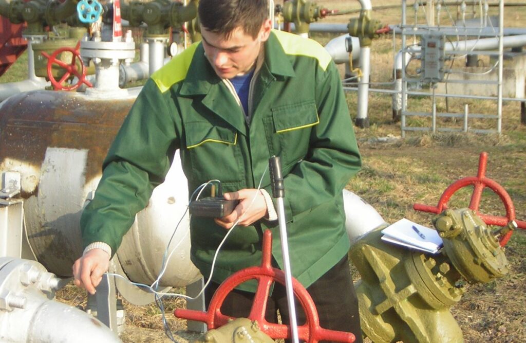
Field Investigation
A stray current investigation begins with an assessment of the pipeline and surrounding electrical environment.
The investigation may include:
- review of pipeline drawings;
- identification of nearby railways;
- identification of neighbouring cathodic protection systems;
- inspection of test stations;
- verification of insulating joints;
- identification of grounding systems;
- review of previous potential measurements;
- identification of known corrosion locations.
This information is used to develop an appropriate field measurement program.
Pipe-to-Soil Potential Monitoring
Structure-to-electrolyte potential monitoring is one of the principal tools for detecting stray current interference.
Measurements may be performed at:
- pipeline test stations;
- railway crossings;
- insulating joints;
- pipeline intersections;
- locations near cathodic protection groundbeds;
- known corrosion areas;
- other critical locations.
Potential measurements can be recorded continuously to identify fluctuations that cannot be detected during conventional periodic inspections.
Long-Term Data Logging
Dynamic interference often requires measurements over an extended period.
Data loggers can be used to continuously record pipeline potentials and other electrical parameters.
Monitoring periods may range from several hours to several days or longer depending on the source of interference.
Long-term recording makes it possible to identify:
- maximum positive potential excursions;
- maximum negative potential excursions;
- duration of interference events;
- repeating patterns;
- correlations with external systems;
- periods of greatest corrosion risk.
Current Measurements
Potential measurements alone may not always provide sufficient information.
Where appropriate, current measurements can be performed to determine whether current is entering or leaving the pipeline.
Possible measurements include:
- bond current;
- drainage current;
- coupon current;
- pipeline current;
- current through insulating joints or mitigation devices.
Current direction is particularly important when identifying possible anodic discharge areas.
Correlation Between Measurement Points
One of the most effective methods for investigating stray currents is simultaneous measurement at several locations.
For example, data loggers can be installed:
- near the suspected source;
- upstream along the pipeline;
- downstream along the pipeline;
- near an insulating joint;
- at a reference location outside the interference zone.
Comparing these datasets can help determine the direction and extent of the electrical influence.
Stray Current Mapping
For complex pipeline systems, multiple measurement locations can be used to develop an interference profile along the route.
This can help identify:
- current pickup zones;
- current discharge zones;
- transition areas;
- pipeline sections affected by dynamic potential fluctuations;
- critical locations requiring mitigation.
GPS/GNSS coordinates can be associated with monitoring locations for integration into pipeline integrity databases.
Insulating Joint Testing
The condition of insulating joints can have a major influence on stray current behaviour.
A failed or electrically bypassed insulating joint can allow external currents to propagate into pipeline sections that would otherwise be isolated.
Italcorr can verify:
- electrical isolation;
- potential difference across the joint;
- unwanted metallic bypasses;
- grounding connections;
- surge protection devices;
- electrical continuity.
Insulating joint performance should therefore be considered during stray current investigations.
Interaction with Cathodic Protection
Stray current can significantly complicate cathodic protection assessment.
Potential measurements affected by external DC currents may fluctuate between apparently well-protected and insufficiently protected conditions.
Therefore, evaluation should consider:
- cathodic protection system operation;
- external interference;
- timing of potential fluctuations;
- current direction;
- reference electrode stability;
- ON/OFF measurements where appropriate.
The objective is to distinguish normal cathodic protection behaviour from external electrical influence.
Identification of Current Pickup and Discharge Areas
An important objective of a stray current investigation is to distinguish between areas where current enters and leaves the pipeline.
Current Pickup Area
Where external current enters the pipeline, the structure generally experiences a more negative potential shift.
Current Discharge Area
Where current leaves the pipeline and enters the electrolyte, the potential may shift in the positive direction.
These discharge areas can represent an increased corrosion risk and therefore require particular attention.
Stray Current Mitigation
Once the interference mechanism has been identified, appropriate mitigation measures can be developed.
Depending on the source and pipeline configuration, possible solutions may include:
- drainage systems;
- controlled electrical bonds;
- polarization cells;
- decoupling devices;
- modification of cathodic protection operating parameters;
- installation or repair of insulating joints;
- grounding modifications;
- installation of additional monitoring points;
- coordination between owners of interacting systems.
The selected solution should reduce harmful interference without creating new corrosion risks on neighbouring structures.
Drainage Systems
A drainage system can provide a controlled path for unwanted current to return to its source rather than leaving the pipeline through the soil.
Depending on the interference conditions, drainage may be:
- direct;
- polarized;
- controlled.
The design of a drainage system requires detailed measurements because an incorrectly configured connection can adversely affect the pipeline or neighbouring structures.
After installation, the system should be tested and monitored to verify its effectiveness.
Interference Between Multiple Pipelines
Pipeline corridors can contain several structures operated by different owners.
Each may have its own cathodic protection system.
The resulting electrical interactions can be complex.
Potential problems include:
- one CP system influencing another pipeline;
- competing cathodic protection currents;
- current transfer through bonds;
- interaction through common grounding;
- changes following modification of one system.
In such cases, simultaneous measurements on several pipelines may be necessary.
Remote Monitoring
Where stray current conditions vary continuously, permanent monitoring can provide significant advantages.
Remote monitoring systems may record:
- pipe-to-soil potentials;
- bond currents;
- drainage currents;
- rectifier output;
- AC voltage;
- alarm conditions.
The data can be transmitted to a central monitoring platform for trend analysis and early detection of abnormal conditions.
Data Analysis
Stray current investigations can generate large datasets.
Technical analysis may include:
- potential versus time graphs;
- current versus time graphs;
- correlation between monitoring locations;
- identification of maximum excursions;
- identification of repeating patterns;
- comparison with railway or industrial operation;
- identification of current pickup and discharge zones;
- comparison before and after mitigation.
This allows the actual interference mechanism to be distinguished from normal measurement variability.
Verification After Mitigation
Installation of a mitigation system should always be followed by verification measurements.
The verification may include:
- potential monitoring;
- current measurements;
- drainage current;
- cathodic protection performance;
- comparison with baseline measurements;
- verification at neighbouring structures.
Long-term monitoring may also be required to confirm that the mitigation remains effective under different operating conditions.
Stray Current Interference Reporting
A technical investigation report may include:
- description of the pipeline;
- cathodic protection system configuration;
- suspected interference sources;
- measurement locations;
- instruments and methodology;
- monitoring period;
- potential recordings;
- current measurements;
- graphical analysis;
- identification of pickup and discharge areas;
- evaluation of corrosion risk;
- proposed mitigation measures;
- verification results;
- recommendations for future monitoring.
The results can be integrated into the operator’s corrosion control and Asset Integrity Management program.
Applications
Italcorr provides stray current interference assessment for:
- gas pipelines;
- oil pipelines;
- water pipelines;
- industrial pipelines;
- firewater networks;
- buried storage systems;
- underground metallic infrastructure;
- pipeline corridors near railways;
- structures located close to other cathodic protection systems.
Why Stray Current Interference Assessment Matters
Stray current corrosion can be highly localized and may progress significantly faster than conventional soil corrosion.
A structured interference investigation helps to:
- identify external electrical influences;
- locate potential current discharge areas;
- evaluate corrosion risk;
- distinguish interference from normal CP behaviour;
- optimize cathodic protection performance;
- select appropriate mitigation measures;
- reduce the risk of localized corrosion;
- protect neighbouring structures;
- improve long-term pipeline reliability.
Italcorr Stray Current Interference Services
Italcorr provides stray current interference investigation, monitoring, analysis and mitigation support for buried pipelines and metallic infrastructure.
Our approach combines cathodic protection measurements, continuous data logging and specialized pipeline diagnostic methods to determine how external electrical currents interact with the protected structure.
Where interference is confirmed, the collected data can be used to develop corrective measures and verify their effectiveness.