
Insulating Joint Testing
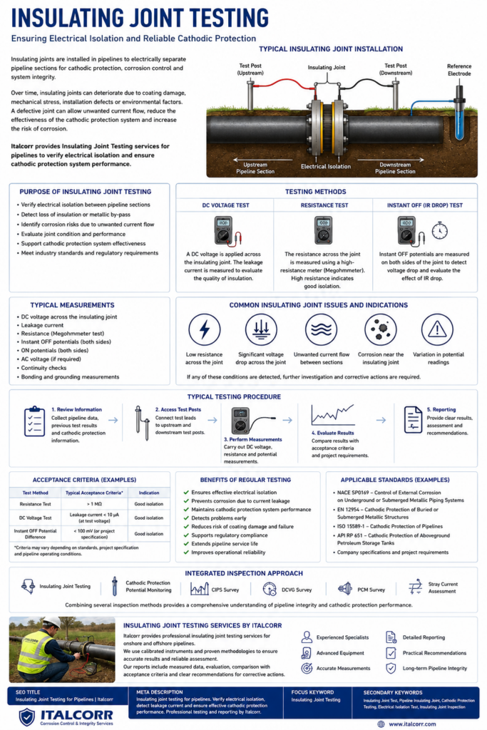
Insulating joints are essential components of cathodic protection systems used on buried and submerged pipelines. Their primary function is to provide electrical isolation between different sections of a pipeline, allowing cathodic protection current to be controlled and preventing unwanted current flow to adjacent metallic structures.
A defective or improperly functioning insulating joint can significantly reduce the effectiveness of a cathodic protection system and may contribute to accelerated corrosion.
Italcorr provides professional Insulating Joint Testing services for pipelines and other metallic structures to verify electrical isolation, identify defects and ensure reliable operation of cathodic protection systems.
What Is an Insulating Joint?
An insulating joint, also known as an isolation joint or insulating flange, electrically separates two sections of a metallic pipeline.
Insulating joints are commonly installed:
- at pipeline stations;
- near compressor and pumping stations;
- at storage facilities;
- at connections between different pipeline systems;
- near cathodic protection boundaries;
- at aboveground-to-underground transitions;
- near industrial facilities;
- where electrical separation between structures is required.
By interrupting metallic electrical continuity, the joint helps keep cathodic protection current within the intended section of the pipeline.
Why Insulating Joint Testing Is Important
The effectiveness of an insulating joint can deteriorate during operation.
Possible causes include:
- moisture penetration;
- contamination;
- deterioration of insulating materials;
- mechanical damage;
- incorrect installation;
- conductive deposits;
- damaged flange insulation;
- electrical bonding through external equipment;
- grounding connections that bypass the joint;
- surge protection devices or other electrical components.
When electrical isolation is lost, cathodic protection current may flow through the joint into another pipeline section or metallic structure.
This can increase current demand, reduce protection levels and create conditions for interference or localized corrosion.
Regular insulating joint testing helps identify these problems before they significantly affect pipeline integrity.
Insulating Joint Testing Methods
Different measurement techniques can be used depending on the pipeline configuration, accessibility of test points and cathodic protection system.
Potential Measurements
Pipe-to-soil potentials are measured on both sides of the insulating joint using a suitable reference electrode.
A comparison of the potentials can provide information about the electrical separation between pipeline sections.
Measurements may include:
- ON potentials;
- Instant OFF potentials;
- potential difference across the joint;
- potential response during cathodic protection interruption.
Significant differences in potential response can indicate effective electrical isolation.
Voltage Measurement Across the Joint
The DC voltage between the two sides of the insulating joint can be measured directly.
The measurement provides useful information about the electrical condition of the joint and can be combined with other testing methods for a more reliable assessment.
Resistance Testing
Electrical resistance across the insulating joint can be measured using appropriate instrumentation.
A properly functioning insulating joint should provide high electrical resistance between the separated pipeline sections.
Low resistance may indicate insulation failure, contamination or an external electrical connection bypassing the joint.
Cathodic Protection Current Interruption
Temporary interruption of the cathodic protection system can be used to observe potential changes on both sides of the insulating joint.
If both pipeline sections respond in a similar way to interruption, this may indicate unwanted electrical continuity.
This method can be particularly useful when evaluating complex pipeline networks.
Detection of Electrical Bypass
An insulating joint itself may be in good condition while another electrical connection creates a bypass around it.
Possible bypass paths include:
- grounding systems;
- electrical cables;
- instrumentation;
- protective devices;
- metallic supports;
- station piping;
- communication equipment;
- surge protection devices.
For this reason, testing should evaluate not only the insulating joint but also the surrounding electrical configuration.
Insulating Joint Testing and Cathodic Protection
Proper electrical isolation is essential for efficient pipeline cathodic protection.
A defective insulating joint can cause protective current to leave the intended pipeline section and flow toward another structure.
Consequences may include:
- insufficient cathodic protection;
- increased rectifier current demand;
- uneven potential distribution;
- interference with neighbouring structures;
- increased energy consumption;
- accelerated corrosion at current discharge locations.
Testing insulating joints therefore forms an important part of cathodic protection system inspection and performance assessment.
Insulating Joint Testing Procedure
A typical inspection begins with a review of the pipeline configuration, cathodic protection system and available test points.
Measurements are then performed on both sides of the insulating joint.
Depending on site conditions, the inspection may include:
- visual inspection of accessible components;
- pipe-to-soil potential measurements;
- voltage measurement across the insulating joint;
- resistance or isolation measurements;
- cathodic protection current interruption;
- verification of grounding and bonding connections;
- investigation of possible electrical bypasses;
- comparison of results with previous measurements;
- evaluation of insulating joint performance.
The results are analysed to determine whether the joint provides adequate electrical isolation.
Common Problems Detected
Insulating joint testing can identify or indicate several problems, including:
- partial insulation failure;
- complete electrical short circuit;
- deterioration of insulating components;
- unintended electrical bonding;
- grounding bypass;
- abnormal current flow;
- unstable potentials;
- interference from neighbouring structures;
- failure of associated electrical components.
Early identification of these conditions can reduce the risk of corrosion damage and unnecessary cathodic protection current losses.
Integration with Pipeline Surveys
Insulating joint testing can be combined with other cathodic protection and pipeline integrity surveys.
Italcorr can integrate insulating joint assessment with:
- CIPS Survey (Close Interval Potential Survey);
- DCVG Survey (Direct Current Voltage Gradient);
- PCM Survey (Pipeline Current Mapping);
- Pearson Survey;
- cathodic protection potential monitoring;
- stray current investigation;
- AC interference assessment;
- soil resistivity measurements.
Combining several diagnostic techniques provides a more complete understanding of cathodic protection performance and pipeline condition.
Applicable Standards
Testing and evaluation of insulating joints should be performed according to applicable international and European standards, project specifications and operator requirements.
Relevant standards may include EN 12954, EN ISO 15589-1 and other requirements applicable to cathodic protection of buried or submerged metallic structures.
The appropriate testing procedure and acceptance criteria depend on the pipeline configuration, cathodic protection system and operating conditions.
Insulating Joint Testing Services by Italcorr
Italcorr provides insulating joint testing and cathodic protection assessment services for pipelines and industrial infrastructure.
Our services include:
- insulating joint inspection;
- electrical isolation testing;
- pipe-to-soil potential measurements;
- voltage measurements across insulating joints;
- resistance measurements;
- Instant OFF measurements;
- cathodic protection interruption testing;
- investigation of electrical bypasses;
- grounding and bonding assessment;
- stray current investigation;
- cathodic protection system performance assessment;
- technical reporting and recommendations.
Properly functioning insulating joints help maintain the required distribution of cathodic protection current, reduce interference between metallic structures and contribute to the long-term corrosion protection and integrity of pipeline systems.