
Cathodic Protection Potential Monitoring
Cathodic Protection Potential Monitoring is a fundamental activity for evaluating the effectiveness and stability of cathodic protection systems applied to buried or submerged metallic structures.
Regular or continuous monitoring of structure-to-electrolyte potential makes it possible to verify whether the protected structure remains within the required protection criteria, identify abnormal potential variations and detect changes in cathodic protection performance before they develop into significant corrosion problems.
Italcorr provides cathodic protection potential monitoring services for pipelines, storage tanks and buried metallic structures, including field measurements, data logging, remote monitoring, analysis and technical reporting.
What Is Cathodic Protection Potential Monitoring?
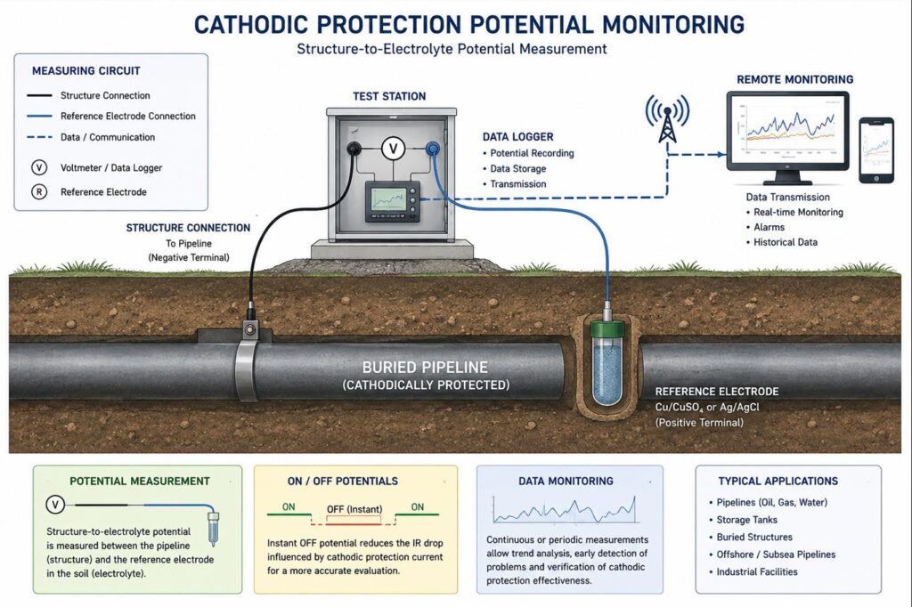
Cathodic protection potential monitoring consists of measuring the electrical potential between a protected metallic structure and a suitable reference electrode placed in the surrounding electrolyte.
For buried pipelines, the measurement is commonly referred to as:
Pipe-to-Soil Potential
For tanks and other structures, the general term:
Structure-to-Electrolyte Potential
is often used.
Potential measurements provide essential information about the electrochemical condition of the protected structure and the performance of the cathodic protection system.
Why Potential Monitoring Is Important
A cathodic protection system cannot be evaluated only by checking whether a transformer-rectifier or sacrificial anode is operating.
The actual objective is to ensure that the structure itself receives sufficient protection.
Potential monitoring can help:
- verify cathodic protection effectiveness;
- identify under-protected areas;
- detect abnormal potential variations;
- identify excessive polarization;
- evaluate CP system stability;
- detect interference from external electrical systems;
- monitor changes in coating condition;
- evaluate seasonal variations;
- support preventive maintenance;
- identify locations requiring detailed investigation.
Long-term monitoring also provides historical information about changes in cathodic protection performance.
Structure-to-Electrolyte Potential
The potential of the protected structure is measured relative to a stable reference electrode.
The reference electrode is placed in electrical contact with the electrolyte, while the measuring instrument is connected to the protected structure.
The measured voltage represents the electrochemical potential difference between the structure and the reference electrode.
Reliable measurements require:
- suitable reference electrode;
- good electrolyte contact;
- high-input-impedance measuring equipment;
- correct polarity;
- reliable structure connection;
- appropriate measurement location.
Reference Electrodes
The type of reference electrode depends on the environment.
Common reference systems include:
- copper/copper sulfate (Cu/CuSO₄);
- silver/silver chloride (Ag/AgCl);
- other reference electrodes appropriate to the electrolyte and application.
For buried pipelines in soil, Cu/CuSO₄ reference electrodes are commonly used.
For marine and seawater applications, Ag/AgCl/seawater reference electrodes are commonly used.
The reference electrode condition should be checked because contamination, dehydration, damage or poor contact can introduce measurement errors.
ON Potential Measurements
The ON potential is measured while the cathodic protection system is operating normally.
ON potential measurements are useful for routine monitoring and provide information about the overall electrical condition of the protected structure.
However, the measured value may include voltage drops in the electrolyte caused by cathodic protection current and other electrical currents.
These components are commonly referred to as IR drop.
For this reason, ON potential measurements should be interpreted carefully when determining the actual polarization condition of the structure.
Instant OFF Potential Monitoring
Where technically appropriate, the cathodic protection current can be interrupted to obtain an instant OFF potential.
The potential is measured immediately after current interruption, before significant depolarization of the structure occurs.
This technique reduces the influence of IR drop and can provide a more representative indication of the polarized condition of the structure.
Where several cathodic protection current sources influence the same structure, synchronized interruption may be required.
Synchronized Current Interruption
For complex pipeline networks, several transformer-rectifier units may simultaneously influence the measured pipeline section.
If only one current source is interrupted, the remaining sources can continue to produce IR drop and influence the measurement.
Synchronized interrupters can therefore be installed on the relevant CP current sources.
This allows:
- simultaneous current interruption;
- consistent ON/OFF cycles;
- reliable instant OFF measurements;
- comparison of measurements at multiple locations;
- detailed CIPS surveys.
Proper synchronization is particularly important for long-distance pipelines protected by several cathodic protection stations.
Permanent Monitoring Points
Cathodic protection potentials can be measured at permanent test stations installed along the protected structure.
Test stations may provide access to:
- pipeline connections;
- reference electrodes;
- coupons;
- insulating joints;
- bonds;
- sacrificial anodes;
- drainage systems.
Periodic measurements at these locations provide a historical record of cathodic protection performance.
Portable Potential Measurements
Portable reference electrodes and high-impedance voltmeters can be used for routine field inspection.
Typical field measurements include:
- pipe-to-soil potential;
- tank-to-soil potential;
- ON potential;
- instant OFF potential;
- native potential;
- potential across insulating joints;
- potential at pipeline crossings;
- potential near suspected interference sources.
Portable measurements are useful for periodic verification and troubleshooting.
Continuous Potential Monitoring
Some electrical conditions cannot be adequately evaluated using a single manual measurement.
Continuous data logging can be used to record potential over:
- minutes;
- hours;
- days;
- weeks;
- longer monitoring periods.
Continuous monitoring is particularly useful when investigating:
- stray currents;
- railway interference;
- unstable cathodic protection systems;
- intermittent electrical interference;
- seasonal changes;
- rectifier operating variations.
Potential-versus-time graphs can reveal patterns that would be missed during occasional measurements.
Remote Cathodic Protection Monitoring
Remote monitoring systems can provide continuous supervision of cathodic protection installations without requiring frequent site visits.
Depending on the system configuration, remote monitoring can record:
- structure-to-electrolyte potential;
- transformer-rectifier voltage;
- transformer-rectifier current;
- AC voltage;
- drainage current;
- bond current;
- reference electrode measurements;
- alarm conditions.
Data can be transmitted to a central monitoring platform for analysis and maintenance planning.
Benefits of Remote Monitoring
Remote monitoring can provide several operational advantages:
- continuous access to CP data;
- early detection of equipment failure;
- identification of abnormal potential changes;
- reduced number of routine site visits;
- faster response to CP system problems;
- historical trend analysis;
- improved maintenance planning.
Remote monitoring does not eliminate the need for periodic field verification, but it can significantly improve the efficiency of cathodic protection management.
Monitoring of Transformer-Rectifier Stations
For impressed current cathodic protection systems, potential monitoring can be combined with measurement of transformer-rectifier operating parameters.
Important parameters include:
- DC output voltage;
- DC output current;
- operating status;
- output stability;
- interruption cycles;
- alarm conditions.
Changes in rectifier output can be correlated with changes in pipeline potential.
This helps distinguish between equipment-related problems and changes in pipeline or environmental conditions.
Monitoring of Sacrificial Anode Systems
Potential monitoring is also essential for structures protected by galvanic anodes.
Measurements can help determine whether sacrificial anodes continue to provide adequate protection.
Monitoring may include:
- structure potential;
- anode potential;
- anode current output;
- circuit resistance;
- potential difference between structure and anode.
Changes over time can indicate anode depletion, electrical connection problems or increasing current demand.
Monitoring at Insulating Joints
Insulating joints influence cathodic protection current distribution and should be included in monitoring programs.
Measurements on both sides of an insulating joint can help identify:
- loss of electrical isolation;
- unintended metallic bypasses;
- interference between pipeline sections;
- abnormal potential differences;
- grounding problems.
Additional electrical testing may be required if joint failure is suspected.
Stray Current Monitoring
Dynamic stray current interference can produce rapid changes in pipeline potential.
Potential monitoring near:
- railways;
- tram systems;
- metro systems;
- neighbouring CP systems;
- industrial DC installations
can help identify the magnitude and duration of these fluctuations.
Simultaneous measurements at several locations can be used to identify possible current pickup and discharge zones.
AC Interference Monitoring
Buried pipelines running parallel to high-voltage AC power systems may also require monitoring for induced AC voltage.
Depending on the project, monitoring can include:
- AC pipe-to-soil voltage;
- DC protection potential;
- grounding system performance;
- mitigation device operation;
- changes associated with power system loading.
AC and DC measurements should be evaluated together where both types of interference are present.
Monitoring Frequency
The appropriate monitoring frequency depends on:
- structure type;
- cathodic protection system;
- corrosion risk;
- regulatory requirements;
- previous inspection results;
- interference conditions;
- environmental conditions;
- criticality of the asset.
Monitoring may be performed periodically or continuously.
Critical locations and structures affected by dynamic electrical interference may require more frequent or permanent monitoring.
Seasonal Variations
Soil conditions can change significantly throughout the year.
Variations in:
- soil moisture;
- temperature;
- groundwater level;
- soil resistivity
can influence cathodic protection current distribution and measured potentials.
For this reason, comparison of measurements taken under different seasonal conditions can provide useful information about system stability.
Trend Analysis
One isolated potential measurement provides information only about conditions at a specific moment.
Historical data are much more valuable for identifying gradual changes.
Trend analysis can reveal:
- decreasing protection levels;
- increasing current demand;
- coating deterioration;
- anode depletion;
- rectifier performance changes;
- development of electrical interference;
- reference electrode instability.
This allows maintenance actions to be planned before protection becomes inadequate.
Potential Monitoring During Commissioning
Potential measurements are an essential part of cathodic protection system commissioning.
Measurements may be taken:
Before energization
To determine native structure potentials.
Immediately after energization
To evaluate the initial response.
After polarization
To verify established cathodic protection conditions.
These measurements create important baseline data for future monitoring.
Potential Monitoring After Repair
Following repair or modification of a cathodic protection system, potential monitoring can verify whether the corrective action has achieved the intended result.
This may be required after:
- rectifier repair;
- anode replacement;
- groundbed installation;
- coating rehabilitation;
- insulating joint repair;
- drainage system modification;
- interference mitigation.
Before-and-after measurements provide objective evidence of system performance.
Data Processing and Analysis
Collected monitoring data can be processed to produce:
- potential-versus-time graphs;
- potential-versus-distance profiles;
- minimum and maximum values;
- statistical trends;
- comparison between test stations;
- correlation with rectifier output;
- correlation with external interference;
- comparison with historical measurements.
Graphical analysis can make gradual changes and short-duration anomalies easier to identify.
Cathodic Protection Criteria
Measured potentials should be evaluated according to the applicable technical standards, project specifications and characteristics of the protected structure.
Assessment may consider:
- ON potential;
- instant OFF potential;
- polarization;
- potential stability;
- IR drop;
- coating condition;
- environmental conditions;
- interference.
A single numerical value should not be interpreted independently from the overall cathodic protection conditions.
Applications
Italcorr provides cathodic protection potential monitoring for:
- gas pipelines;
- oil pipelines;
- water pipelines;
- firewater pipelines;
- industrial pipelines;
- aboveground storage tanks;
- underground storage tanks;
- buried metallic structures;
- steel foundations;
- industrial facilities;
- utility networks.
Integrated Cathodic Protection Monitoring
For comprehensive assessment, Italcorr can combine potential monitoring with:
CIPS Survey
Detailed potential measurements along buried pipelines.
DCVG Survey
Identification of coating defects.
PCM Survey
Evaluation of current attenuation and distribution.
Pearson Survey
Detection of coating discontinuities.
Stray Current Interference Assessment
Investigation of external DC interference.
Insulating Joint Testing
Verification of electrical isolation.
AC Interference Assessment
Evaluation of induced AC effects.
The integration of these methods provides a more complete understanding of both the cathodic protection system and the condition of the protected structure.
Cathodic Protection Monitoring Report
A technical report may include:
- description of the protected structure;
- cathodic protection system configuration;
- measurement locations;
- reference electrodes used;
- measurement methodology;
- ON potentials;
- instant OFF potentials where applicable;
- rectifier operating parameters;
- monitoring period;
- potential-versus-time graphs;
- historical comparisons;
- identified anomalies;
- assessment of CP effectiveness;
- recommendations for corrective actions;
- recommendations for future monitoring.
Benefits of Cathodic Protection Potential Monitoring
A structured monitoring program helps to:
- verify continuous corrosion protection;
- detect under-protected areas;
- identify CP system failures;
- detect abnormal potential fluctuations;
- identify electrical interference;
- optimize rectifier operation;
- evaluate system performance over time;
- reduce unnecessary maintenance;
- support preventive maintenance;
- provide historical CP records;
- improve long-term asset integrity.
Cathodic Protection Potential Monitoring by Italcorr
Italcorr provides cathodic protection potential monitoring for buried and submerged metallic structures, from routine field measurements to continuous data logging and remote monitoring.
Measurement data are analysed together with cathodic protection system parameters and, where necessary, integrated with CIPS, DCVG, PCM, Pearson and interference investigations.
This approach allows changes in cathodic protection performance to be identified early and provides reliable technical information for corrosion control, maintenance planning and Asset Integrity Management.