Soil Resistivity Measurements
Soil Resistivity Measurements are an essential part of corrosion assessment and the design, installation and evaluation of cathodic protection systems for buried metallic structures.
Soil resistivity indicates how strongly the soil resists the flow of electrical current. It is an important parameter because it influences both the corrosivity of the environment and the electrical performance of cathodic protection systems.
Italcorr provides professional soil resistivity measurement services for pipelines, storage tanks, buried structures, cathodic protection systems and industrial infrastructure, including field measurements, data analysis and technical reporting.
What Is Soil Resistivity?
Soil resistivity is a physical property that describes the resistance of a volume of soil to electrical current flow.
It is normally expressed in:
Ω·m (ohm-metres)
or, depending on the measurement system:
Ω·cm (ohm-centimetres).
Soil resistivity depends on several environmental factors, including:
- soil composition;
- moisture content;
- dissolved salts;
- temperature;
- porosity;
- groundwater conditions;
- soil compaction;
- depth;
- seasonal variations.
Because these parameters can vary considerably along a pipeline route or industrial site, soil resistivity should normally be measured at representative locations rather than assumed from general soil classifications.
Why Soil Resistivity Is Important
Soil resistivity affects the behaviour of buried metallic structures in two important ways.
First, it provides useful information about the electrical characteristics of the surrounding environment and can support the assessment of external corrosion conditions.
Second, soil resistivity directly influences the design and performance of cathodic protection systems.
It is particularly important for:
- cathodic protection system design;
- anode selection;
- groundbed design;
- calculation of anode resistance;
- evaluation of current distribution;
- assessment of buried pipeline environments;
- selection of locations for anode installation;
- corrosion investigations.
Reliable resistivity data therefore provide an important engineering basis for designing effective corrosion protection systems.
Soil Resistivity and Corrosion
In general, low-resistivity soils allow electrical current to flow more easily and may be associated with environments capable of supporting higher electrochemical corrosion activity.
Higher-resistivity soils restrict current flow.
However, soil resistivity alone should not be used as the only indicator of soil corrosivity.
A complete corrosion assessment may also consider:
- soil pH;
- moisture;
- chlorides;
- sulphates;
- oxygen availability;
- microbiological activity;
- redox conditions;
- coating condition;
- stray currents;
- cathodic protection performance.
Soil resistivity should therefore be considered as one component of a broader corrosion engineering assessment.
Wenner Four-Pin Method
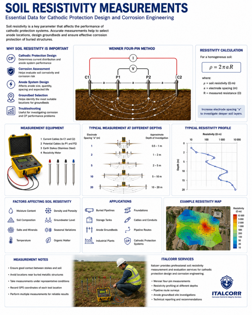
One of the most widely used methods for field measurement of soil resistivity is the Wenner Four-Pin Method.
Four electrodes are installed in a straight line in the soil at equal spacing.
An electrical current is passed through the two outer electrodes, while the voltage difference is measured between the two inner electrodes.
The instrument determines the resistance of the soil, which is then used to calculate apparent soil resistivity.
For approximately homogeneous soil and appropriate electrode geometry, the relationship is commonly expressed as:
ρ = 2πaR
where:
ρ = apparent soil resistivity;
a = spacing between adjacent electrodes;
R = measured resistance.
The actual interpretation should consider electrode depth, soil layering and field conditions.
Measurements at Different Depths
Changing the spacing between the Wenner electrodes allows the electrical properties of different soil volumes to be investigated.
Small electrode spacing primarily represents shallow soil conditions.
Increasing the spacing increases the effective investigation depth.
Measurements at several spacings can therefore provide information about changes in soil resistivity with depth.
This is particularly useful when designing deep or distributed cathodic protection groundbeds.
Soil Resistivity Along Pipeline Routes
Soil conditions can change significantly along long-distance pipelines.
Variations may occur because of:
- different geological formations;
- groundwater;
- rivers and wetlands;
- agricultural areas;
- rocky terrain;
- backfill materials;
- industrial areas;
- changes in soil moisture.
For pipeline projects, measurements can be performed at selected intervals along the route and at locations where significant changes in terrain or soil conditions occur.
The results can be presented as a soil resistivity profile versus pipeline chainage.
Cathodic Protection System Design
Soil resistivity is a fundamental input for cathodic protection engineering.
It affects:
- anode-to-earth resistance;
- required anode quantity;
- groundbed dimensions;
- anode spacing;
- expected current output;
- operating voltage;
- energy consumption;
- expected system performance.
For impressed current cathodic protection systems, soil resistivity measurements are particularly important when selecting the location and configuration of the anode groundbed.
Anode Groundbed Design
The performance of an impressed current groundbed depends strongly on the electrical resistance between the anodes and the surrounding soil.
A groundbed installed in high-resistivity soil may require significantly higher operating voltage to provide the required protective current.
Measurements can therefore be performed at several candidate locations before the final groundbed position is selected.
The investigation may include different electrode spacings to evaluate soil conditions at the expected installation depth.
Sacrificial Anode Systems
Soil resistivity also affects the performance of galvanic anodes.
The available current from a sacrificial anode depends partly on the electrical resistance between the anode and the surrounding soil.
For this reason, resistivity data are useful when determining:
- anode material;
- anode dimensions;
- number of anodes;
- installation depth;
- anode spacing;
- expected current output;
- expected operating life.
The cathodic protection design should consider both current requirements and the actual electrical characteristics of the soil.
Soil Resistivity for Storage Tanks
Soil or foundation resistivity measurements can also be important when designing cathodic protection systems for aboveground and underground storage tanks.
For aboveground tanks, the properties of the material beneath the tank bottom can significantly influence CP current distribution.
Measurements may be required for:
- natural soil;
- sand foundations;
- backfill materials;
- proposed anode installation zones.
The results can be used when selecting anode configuration and estimating system resistance.
Seasonal Variations
Soil resistivity can vary throughout the year.
Important influences include:
- rainfall;
- drought;
- groundwater level;
- soil temperature;
- freezing;
- evaporation.
Dry soil generally has higher resistivity than the same soil under moist conditions.
Where seasonal variations are expected to be significant, measurements performed at different times can provide a more representative understanding of site conditions.
Field Measurement Procedure
A typical Soil Resistivity Measurement program includes:
- selection of measurement locations;
- inspection of local site conditions;
- installation of four electrodes;
- verification of equal electrode spacing;
- resistance measurement;
- repetition at different electrode spacings where required;
- recording of GPS/GNSS coordinates;
- documentation of soil and environmental conditions;
- calculation of apparent soil resistivity;
- analysis and interpretation of results.
Multiple measurements may be performed to verify repeatability and identify local anomalies.
Factors Affecting Measurements
Several factors can influence soil resistivity results.
These include:
- buried pipelines;
- electrical cables;
- grounding systems;
- reinforcement;
- fences;
- nearby metallic structures;
- poor electrode contact;
- very dry surface soil;
- uneven electrode spacing;
- electrical interference.
Measurement locations should therefore be selected carefully.
Where possible, electrodes should be positioned away from large buried metallic objects that could distort the electrical field.
Data Analysis
Measurement results can be processed to determine:
- resistivity at individual locations;
- variation with electrode spacing;
- variation with depth;
- variation along a pipeline route;
- minimum and maximum measured values;
- average site conditions;
- areas of unusually low or high resistivity.
For larger projects, results can be presented graphically or integrated with GIS data.
Soil Resistivity Mapping
For pipelines and large industrial sites, multiple measurement points can be used to create a resistivity map or route profile.
This helps identify:
- low-resistivity areas;
- high-resistivity areas;
- changes in soil conditions;
- potential groundbed locations;
- areas requiring additional investigation.
GPS/GNSS coordinates can be recorded for each measurement point to allow accurate mapping and future verification.
Integration with Cathodic Protection Surveys
Soil resistivity measurements can be combined with other cathodic protection and corrosion assessment techniques.
Italcorr can integrate soil resistivity measurements with:
CIPS Survey – assessment of cathodic protection potential distribution.
DCVG Survey – localization and assessment of pipeline coating defects.
PCM Survey – evaluation of pipeline current distribution.
Pearson Survey – detection of coating defects.
Potential Monitoring – evaluation of cathodic protection performance over time.
Stray Current Assessment – investigation of external DC interference.
Correlation of environmental and electrical data provides a more complete understanding of pipeline corrosion conditions.
Applications
Soil Resistivity Measurements can be performed for:
- oil and gas pipelines;
- water pipelines;
- industrial pipelines;
- cathodic protection groundbeds;
- aboveground storage tanks;
- underground storage tanks;
- buried metallic structures;
- steel foundations;
- industrial plants;
- terminals and depots;
- grounding and corrosion investigations.
Soil Resistivity Measurement Report
A technical report may include:
- project and site description;
- measurement methodology;
- equipment used;
- electrode spacing;
- GPS coordinates;
- measured resistance;
- calculated soil resistivity;
- soil conditions;
- environmental observations;
- resistivity tables;
- graphical profiles;
- interpretation of results;
- recommendations for cathodic protection design.
For pipeline projects, results can also be referenced to pipeline chainage.
Soil Resistivity Measurements by Italcorr
Italcorr provides Soil Resistivity Measurements for cathodic protection design, corrosion assessment and buried infrastructure projects.
Measurements can be performed at individual structures, industrial facilities or at multiple locations along pipeline routes.
The collected data can be used for anode selection, groundbed design, cathodic protection calculations and evaluation of environmental conditions, providing reliable field information for corrosion engineering decisions.